

close
Choose Your Site
Global
Social Media
Views: 0 Author: Site Editor Publish Time: 2026-08-03 Origin: Site


Deep pockets, lapped joints, tube interiors, and welded seams are usually where corrosion protection is hardest to make dependable. A spray pattern must see a surface to coat it well; an Electrophoretic Coating Line works from a different principle. The immersed conductive part becomes an electrode, so charged coating particles move through the bath under an electric field. That makes it possible to build film on many hard-to-reach surfaces, but it does not make every geometry equally easy. Good coverage depends on the part design, electrical path, bath condition, racking, and rinse sequence working together.
E-coating reaches hidden conductive surfaces because deposition is driven by an electric field in an immersion bath, not only by direct spray access.
The deposited film becomes increasingly resistive, which helps redirect deposition toward less-coated areas but can also expose weak electrical access in very deep cavities.
Narrow, shielded recesses and poorly vented overlaps may still need changes to rack position, drainage, anode placement, voltage profile, or the part itself.
Weld seam quality begins before coating: weld spatter, oil, oxides, trapped solution, and sharp crevices can interrupt a protective film.
An electrophoretic process begins after cleaning and pretreatment, when the workpiece enters a water-based coating bath. Direct current establishes the electrical condition for charged resin and pigment particles to travel toward the conductive substrate. As particles deposit, the layer starts to insulate the already-coated area. Current is then less able to continue through that surface, so deposition tends to continue where the film is thinner or absent. This self-limiting behavior is a major reason an e-coat film can be more even across a complex part than a line-of-sight application.
The useful word is “tends.” Throwing power is not a promise that every concealed surface receives the same film build. Electrical field strength changes with distance, opening size, obstruction, anode position, and the path available through the bath. A deep rectangular pocket with a narrow mouth has a different challenge from a wide channel, an enclosed tube, or a lap joint. Parts also travel through the tank together, so an adjacent large panel or a tightly packed rack can affect the local field available to a smaller feature.
For programs involving automotive components, metal hardware, and heavy machinery, a system should therefore be assessed as a complete process. BONITA MACHINERY presents its electrophoretic coating line solutions for these metal-finishing applications; the final configuration still needs to be matched to the actual workpiece and production conditions.
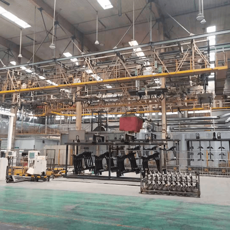
At the start of deposition, bath liquid must reach the recess, displace air, and form an electrically continuous path to the surface. If a cavity is partly sealed, an air pocket can block liquid contact. If it drains poorly, pretreatment chemicals or rinse water can remain in the feature and later contaminate the coating stage or curing process. Orientation on the rack is therefore a coverage control, not simply a handling choice.
Once the cavity is filled, the field must extend far enough into it. The outer edges generally see a stronger field and begin building film first. A gradual, controlled voltage rise gives the interior more opportunity to participate before the accessible surfaces become too resistive. An aggressive start may build the outer film quickly while doing little for a remote internal wall. The correct electrical profile depends on paint chemistry, part geometry, tank arrangement, and the supplier’s validated process window; it should not be set from a generic voltage value.
As the outer surface gains film thickness, its electrical resistance rises. This reduces further deposition there and can favor areas that have received less coating. That is why an electrophoretic coating line is often selected for recessed metal parts. Yet the effect cannot overcome an absent liquid path, a fully shielded cavity, or an anode that is simply too remote from a deep interior surface.
The practical objective is not merely “maximum voltage.” It is a stable balance among voltage rise, deposition time, bath conductivity, solids control, temperature, circulation, and the electrical geometry of the load. Raising voltage indiscriminately can make exterior build faster and may worsen appearance or create film faults. A trial part, cut-section examination, and corrosion-performance verification are more useful than relying on the visual appearance of the exterior alone.
Weld seams bring a different set of risks. A continuous, accessible seam can receive e-coat well, but a seam is rarely as smooth or uniform as adjacent base metal. Spatter, burn residue, grinding dust, weld scale, handling oil, and sharp edges can interfere with pretreatment or create local film irregularity. A lap weld can also create a capillary-like crevice that collects process liquid. If the liquid cannot rinse and drain, a coating operation may hide rather than solve the underlying corrosion risk.
Before commissioning a part, review the weld design with the coating sequence in mind. Continuous welds where sealing is required, rounded transitions where feasible, accessible drain and vent openings, and a defined cleaning method all improve processability. Discontinuous seams or intentional gaps may be appropriate for fabrication or drainage in some products, but they must be evaluated against the corrosion environment because an unsealed overlap can hold moisture in service.
Pretreatment is equally important. E-coat cannot bond reliably through oil, loose oxide, or residues. Cleaning, rinsing, conversion treatment where specified, and final rinsing should be designed for the same difficult regions that the coating bath must reach. If a seam is not clean and wettable before electrodeposition, the final film will not create a dependable barrier merely because it looks covered after baking.
The Faraday cage effect is often used to describe poor deposition in interior corners, narrow boxes, and enclosed shapes. The general mechanism is simple: field lines favor accessible paths, and early film build on the exterior increases resistance before an interior zone has been coated adequately. The corrective action depends on the cause.
Condition observed | Likely process question | Useful response to evaluate |
|---|---|---|
Bare or thin area at the bottom of a pocket | Is the electrical path too long or the pocket opening too restricted? | Review part orientation, anode geometry, voltage ramp, and whether an auxiliary anode is warranted. |
Inconsistent coverage only on some racks | Are parts shielding one another or hanging differently? | Standardize rack spacing, grounding contact, load pattern, and orientation. |
Local film disturbance near a weld overlap | Is trapped chemistry or gas escaping during cure? | Check weld design, cleaning access, rinse drainage, and venting before changing electrical settings. |
Heavy exterior build with weak interior coverage | Is voltage rising too quickly for the part geometry? | Validate a gentler power profile and compare sectioned-film results, not exterior gloss alone. |
Auxiliary anodes can shorten the electrical path to an otherwise remote interior surface. They are a tooling and line-design decision, not a universal add-on. They must be protected, maintained, and positioned so that they improve coverage without creating new nonuniformity. Part-specific jigs may also be the better answer: tilting an open cavity so air escapes and liquid drains can matter more than adding electrical complexity.
An e-coat line treats the rack, hook, contact point, and workpiece as part of one electrical circuit. A corroded or paint-covered contact can raise resistance and create inconsistent deposition. The contact location also leaves a small area that may need to be hidden, masked, or otherwise acceptable in the part specification. For a welded assembly, confirm that the electrical path reaches all intended conductive sections; isolated inserts, loose joints, and nonconductive sealants change what can be coated.
Load density deserves the same attention. Packing too many large parts together can change circulation, trap air, and shade openings from the field. A rack pattern that maximizes pieces per carrier may reduce the certainty of coverage on recesses. The best loading plan balances throughput with the ability to clean, immerse, coat, rinse, drain, and cure every critical surface repeatably.
This is why a process review should use representative worst-case parts rather than only simple panels. Include the deepest recess, the tightest tube, the heaviest welded assembly, and the minimum and maximum production load. Inspect interior surfaces after cure and record which rack orientation and electrical settings were used. That produces a repeatable starting point for control plans and changeover procedures.
Before specifying an electrophoretic coating line, provide the equipment team with drawings or samples that show recess depth, opening dimensions, enclosed volumes, seam type, drainage holes, target corrosion exposure, and any noncoated areas. Ask how the proposed anode arrangement, conveyor path, rack design, bath circulation, and ultrafiltration rinse stages address those features. Request a trial plan that includes film-thickness checks at interior locations and a clear method for evaluating the seam after pretreatment and cure.
It is also sensible to separate a coating claim from a finished-product claim. The line can be configured for consistent immersion, power control, rinsing, and curing, but the corrosion result also depends on substrate condition, paint system, part design, and validated operating parameters. For a high-volume program, a pilot run with deliberately difficult parts is a better purchasing input than a generic promise of complete coverage.
Validation should follow the real failure risk rather than convenience. Exterior faces are easy to inspect and often look satisfactory even when a narrow return, weld overlap, or internal pocket has limited film. Choose defined measurement and section locations before the trial begins. If corrosion testing is part of the product requirement, agree in advance how samples are prepared, where coating thickness is assessed, and how a failure location will be interpreted. This avoids the situation in which one team approves a glossy exterior while another later finds an unprotected feature.
Repeat the trial at normal and challenging conditions: a typical load, the expected maximum load, and the arrangement most likely to trap air or restrict access. If the process changes—new weld design, different substrate, modified rack, altered paint chemistry, or changed conveyor speed—treat the coverage check as a revalidation trigger. That discipline keeps a successful launch setting from becoming an unsupported assumption.
An Electrophoretic Coating Line can cover recesses and weld seams more effectively than line-of-sight methods because electrical deposition continues across immersed conductive surfaces. The result is strongest when the design supports filling, current access, rinsing, and drainage. Treating difficult geometry as a joint part-design and process-control problem prevents costly late changes. BONITA MACHINERY can configure coating-line modules for different load types, while buyers should validate coverage on their own deepest cavities and most demanding welded assemblies before fixing the production specification.
It can coat accessible conductive tube interiors when the bath can enter, air can escape, and the electrical path is sufficient. Very long or narrow tubes may require part-specific orientation, anode design, or a geometry review.
No. A higher or faster voltage rise can increase exterior deposition before the interior receives adequate film. A controlled, validated power profile is usually more useful than simply increasing the setpoint.
Weld areas may retain spatter, oxide, oil, moisture, or residues, and overlaps can trap process liquid. Cleaning, pretreatment access, seam design, drainage, and curing conditions all affect the final protection.
It describes electrical shielding that reduces deposition in recessed or enclosed areas. It is managed by considering geometry, anode position, rack orientation, bath control, and the voltage profile together.
No. An auxiliary anode is useful only where the normal electrical path does not give sufficient coverage. It should follow a trial and line-design review, because it adds maintenance and control considerations.


