

close
Choose Your Site
Global
Social Media
Views: 0 Author: Site Editor Publish Time: 2026-08-26 Origin: Site


In industrial finishing, the stability of the electrical field dictates coating quality. Minor fluctuations in bath conductivity compromise film thickness, adhesion, and corrosion resistance. Uncontrolled conductivity leads to high reject rates, increased paint consumption, and costly downtime. Contamination from metal ions, pre-treatment carryover, or aging paint rapidly destabilizes the bath chemistry. Modern systems rely on closed-loop filtration, precise deionized (DI) water integration, and automated monitoring to maintain equilibrium. This guide examines the mechanical and chemical controls required to manage bath conductivity. We provide a framework for evaluating system capabilities when upgrading or specifying a new electrophoretic coating line. You will learn how to isolate pre-treatment zones, manage permeate purging, and calibrate inline sensors to keep your deposition process locked within strict operational windows.
Ultrafiltration is Non-Negotiable: Effective conductivity control relies on continuous ultrafiltration to drain exudate and remove excess water-soluble salts, especially when introducing fresh paint solutions.
Strict Water Quality Standards: The conductivity of cleaning and makeup water must be strictly maintained below 10 μs/cm using industrial-grade Deionized (DI) water systems.
Pre-Treatment Isolation: Preventing metal ion carryover from phosphating or cleaning stages via dedicated pre-electrophoresis DI rinsing is the most cost-effective method for preventing sudden conductivity spikes.
Automated Monitoring vs. Manual Intervention: High-volume operations, such as an Automotive E-Coating Line, require inline, temperature-compensated conductivity sensors integrated with automated dosing and filtration controls to prevent calibration drift and human error.
The electrophoretic deposition process operates as a massive direct current (DC) circuit. The rectifier supplies the DC power. Heavy copper busbars carry the current to the anode cells and the part hanger. The metallic substrate acts as one electrode. A series of counter-electrodes positioned along the tank walls completes the circuit. Direct current flows through the liquid bath, driving the chemical reaction. The bath liquid acts as the conductive medium. High bath liquid conductivity facilitates the active sweeping and deposition of paint particles onto the substrate.
The deposition process breaks down into four distinct physical phases:
Electrolysis: Water splits at the electrodes, generating oxygen at the anode and hydrogen at the cathode.
Electrophoresis: Charged resin and pigment micelles migrate toward the substrate under the influence of the electrical field.
Electrodeposition: The micelles lose their charge upon reaching the substrate, coagulating into an insoluble film.
Electro-osmosis: The electrical field squeezes water out of the deposited film, compacting it into a dense layer.
Conductivity directly dictates how easily current travels through the fluid during these phases. When conductivity remains stable, the electrical resistance of the bath stays predictable. Predictable resistance allows the applied voltage to deposit a uniform film build across complex geometries. If conductivity drops, the bath resists current flow. The system struggles to push paint particles into recessed areas. If conductivity spikes, current flows too rapidly. This rapid flow forces excessive paint onto the outer surfaces of the part.
Bath temperature shares a strict relationship with conductivity. As bath temperature rises, fluid viscosity decreases. Lower viscosity increases ion mobility. Higher ion mobility immediately raises the electrical conductivity of the bath. A temperature shift of just one degree Celsius alters conductivity readings by up to two percent. Heat exchangers must hold the bath temperature within a tight one-degree tolerance to maintain baseline electrical stability. If a chiller fails on the factory floor, the bath temperature climbs, conductivity spikes, and the line immediately begins producing defective parts.
Different paint chemistries demand specific operating windows. Cathodic epoxy systems generally operate between 1000 and 1500 μS/cm. Anodic acrylic systems run at slightly different parameters based on resin solids and solvent content. Plant managers establish a strict upper and lower control limit for their specific paint formulation based on the manufacturer's technical data sheet.
Operating outside these established parameters guarantees defects. Low conductivity causes thin, uneven coats. The paint lacks the electrical driving force to penetrate Faraday cage areas. Parts emerge with bare interior cavities and inadequate corrosion protection. High conductivity causes severe film ruptures. The aggressive current flow generates excessive gas bubbles at the part surface. These bubbles become trapped in the curing paint, causing pinholing, cratering, and a rough surface texture. High conductivity also causes excessive current draw, straining rectifiers and wasting electrical energy.
Operators frequently attempt to mask conductivity drift by tweaking rectifier voltage. If the film build drops due to low conductivity, they turn up the voltage from 250V to 300V. Voltage adjustments alter the deposition speed but do not fix the underlying chemical imbalance. Relying on voltage tweaks instead of addressing root-cause conductivity issues generates excess heat and accelerates paint degradation. Evaluating process stability requires tracking conductivity, pH, and temperature simultaneously over a 30-day production cycle. Consistent metrics indicate a healthy, stable process.
The majority of sudden conductivity spikes originate upstream. Parts travel through intensive cleaning and phosphating stages before reaching the e-coat tank. These pre-treatment stages utilize heavy metal salts, acids, and alkaline cleaners. Inadequate rinsing allows these chemicals to pool in the crevices of the metal parts. Consider a fabricated steel frame with tubular sections. The tubes fill with cleaning chemicals. If the line lacks proper tilt stations or blow-off nozzles, those tubes carry gallons of highly conductive liquid into the e-coat tank.
Zinc, iron, and phosphate ions are highly conductive. When introduced into the e-coat tank, they immediately elevate the bath conductivity. These foreign ions disrupt the micelle stability of the paint emulsion. E-coat paint relies on a delicate balance of neutralizers to keep resin particles suspended in water. Heavy metal ions attack these neutralizers. This chemical reaction causes localized conductivity spikes and forces the paint to coagulate. Coagulated paint forms gritty deposits on the parts and clogs filtration systems.
Preventing this carryover requires a dedicated, multi-stage DI water rinse immediately preceding the e-coat tank. This final rinse zone acts as a physical barrier against conductive contaminants. The DI water flushes residual salts from the part seams. Without this isolation stage, the e-coat bath suffers continuous contamination and rapid chemical degradation.
Conductivity shifts naturally due to paint consumption and replenishment. Fresh paint solutions possess inherently high conductivity. Paint manufacturers load fresh resin and paste with high levels of solvents and acid neutralizers to keep the paint stable during shipping and storage. When operators introduce fresh paint into the tank, the sudden influx of neutralizers causes the bath conductivity to rise.
Maintaining a consistent production volume prevents the bath chemistry from stagnating. Industry professionals refer to this as the paint turnover rate. The turnover rate measures how quickly the production line consumes and replaces the entire volume of paint solids in the tank. You calculate this by tracking the total square footage of metal coated and multiplying it by the target film thickness. A high turnover rate keeps the bath fresh and stable. A low turnover rate allows the paint to age. As paint ages, solvents evaporate into the exhaust system. The ratio of water to solids shifts, causing conductivity to drift out of specification.
During the deposition process, the electrical current drives resin and pigment onto the part. The acid or amine neutralizers remain behind in the bath. Over time, these neutralizers accumulate. This buildup of residual chemicals steadily increases the bulk conductivity of the tank. The system must actively remove these excess neutralizers to maintain equilibrium.
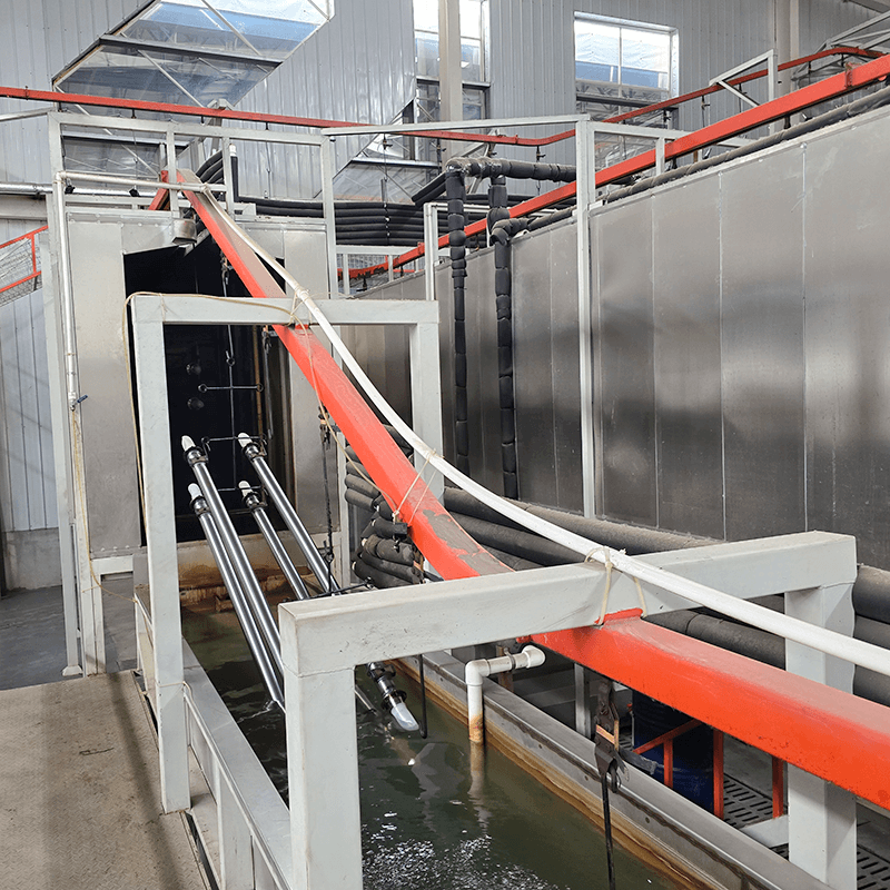
Ultrafiltration provides the primary mechanical defense against rising conductivity. A standard UF skid includes a feed pump, a massive circulation pump, and multiple membrane housings plumbed in parallel. The feed pump pulls paint from the main tank and pushes it into the circulation loop. The circulation pump drives the paint through the membrane tubes at high velocity. This high velocity prevents the paint solids from packing against the membrane walls. The pressure forces water, solvents, and dissolved salts through the membrane pores. This clear liquid is called permeate. The membrane blocks the larger resin and pigment particles, returning them to the main tank.
Permeate contains the excess water-soluble salts and neutralizers that drive up conductivity. By draining a portion of this exudate out of the system, operators physically purge conductive ions from the bath. This purging process manages the initial surge of solvents and neutralizers introduced by new paint additions.
Facilities choose between closed-loop permeate recycling and open-loop purging. Closed-loop systems route all permeate to the post-rinse zones and eventually back into the main tank. This saves water but traps conductive salts inside the system. Open-loop systems route a percentage of the permeate directly to the wastewater treatment plant. This effectively lowers bath conductivity but increases waste disposal costs.
Permeate Management Strategies
Strategy | Conductivity Impact | Operational Cost | Best Application |
|---|---|---|---|
Closed-Loop Recycling | Retains salts; conductivity slowly rises over time. | Low water usage; minimal wastewater treatment required. | High-volume lines with low pre-treatment drag-out. |
Open-Loop Purging | Actively reduces conductivity by removing dissolved ions. | High water usage; increased wastewater processing costs. | Lines experiencing frequent contamination or heavy fresh paint additions. |
Hybrid RO Recovery | Excellent conductivity control; extracts pure water from permeate. | High initial capital expenditure; moderate maintenance. | Strict environmental compliance zones demanding zero liquid discharge. |
Purging permeate removes liquid volume from the e-coat tank. The system must replace this lost volume with exceptionally pure water. All pure water used in the tank and final cleaning stages must maintain a conductivity of less than 10 μs/cm. Using standard city water introduces calcium, magnesium, and chlorides directly into the paint. City water typically measures around 300 μS/cm and will ruin the bath chemistry within hours.
A robust DI water generation system forms the backbone of any reliable Automotive E-Coating Line. The architecture involves carbon filters to remove chlorine, followed by reverse osmosis (RO) units, and finally mixed-bed deionization tanks. The RO units strip out 98% of the dissolved solids. The mixed-bed DI tanks polish the water, removing the final trace ions to achieve the sub-10 μs/cm requirement.
Monitoring the DI water plant requires daily checks. Operators record the inlet water pressure, the RO pump pressure, and the final conductivity of the mixed-bed resin tanks. When the resin exhausts its ion-exchange capacity, the conductivity spikes. The system must automatically divert this off-spec water to the drain and trigger an alarm. This high-purity DI water acts as the makeup water for the main tank and feeds the final pre-treatment rinse halos.
While UF systems manage bulk bath conductivity, the anolyte system manages localized chemical imbalances at the electrodes. In a cathodic e-coat system, the parts act as the cathode. The counter-electrodes act as the anodes. These anodes are typically constructed from stainless steel or ruthenium oxide and sit inside plastic boxes. One side of the box features a semi-permeable membrane.
As paint deposits onto the parts, excess acid neutralizers migrate toward the anodes. If left unchecked, this acid pools around the anodes, severely disrupting the electrical field, spiking conductivity, and dissolving the anode material. An independent circulation system flushes these cells with a specialized fluid called anolyte. The anolyte fluid captures the excess acid generated during deposition and carries it to a secondary tank.
The anolyte system requires its own dedicated conductivity controller. The anolyte fluid is highly acidic, typically running between 5000 and 8000 μS/cm. The controller constantly monitors this value. When the value hits the upper setpoint, a solenoid valve opens. Fresh DI water floods into the anolyte circulation tank. The excess acidic fluid overflows a weir and goes to the wastewater treatment plant. This continuous bleed-and-feed process keeps the anode cells clean and maintains the electrical field strength.
Manual conductivity checks using handheld meters invite human error and delay adjustments. High-volume production requires inline, continuous monitoring. Standard contacting sensors utilize metal prongs exposed directly to the fluid. In an e-coat tank, paint rapidly deposits onto these metal prongs, insulating them. This fouling causes the sensor to report falsely low conductivity readings. The system under-compensates, allowing actual tank conductivity to climb dangerously high.
Modern lines require inline, temperature-compensated toroidal conductivity sensors. Toroidal sensors use inductive magnetic coils encased in a smooth polymer housing. Because they have no exposed metal contacts, paint cannot insulate the reading mechanism. These electrodeless sensors provide highly accurate, drift-free measurements even in thick paint emulsions.
Advanced programmable logic controllers (PLCs) translate sensor data into automated actions. If the toroidal sensor detects a conductivity spike, the PLC automatically opens the UF purge valves. Simultaneously, the PLC triggers the DI water makeup system to replace the purged volume. It runs this loop until conductivity drops back to the target setpoint. This automated loop eliminates the need for manual intervention.
When specifying a new line, engineers size the UF and DI systems based on total production volume, part surface area, and drag-out rates. Large parts with complex geometries carry more liquid out of the tank. If a car body drags out 5 gallons of liquid and the line processes 30 cars an hour, the system loses 150 gallons an hour to drag-out. The UF system must produce at least 150 gallons an hour of permeate just to feed the post-rinses. To allow for permeate purging, engineers oversize the UF capacity by at least 50 percent.
Modular filtration designs offer significant advantages. A modular UF skid allows plant managers to add extra membrane housings as production scales up. If the facility increases line speed, they expand the UF capacity without requiring a full line redesign. Installing oversized RO pumps initially allows for easy expansion of the DI water membrane arrays later.
Conductivity management directly impacts environmental compliance. Purging high-conductivity permeate effectively stabilizes the bath, but it generates industrial wastewater. Permeate contains heavy metals, dissolved solvents, and organic compounds. Facilities add chemicals to drop the metals into a sludge, press the sludge, and send it to a landfill. This process drives up operational costs.
Plant managers balance maintaining optimal bath chemistry against minimizing wastewater treatment burdens. Advanced facilities deploy secondary reverse osmosis (RO) recovery systems on their permeate lines. The RO system processes the purged permeate, extracting clean water and returning it to the rinse zones. It concentrates the heavy metals and organics into a much smaller volume of waste. This technology minimizes environmental impact while allowing aggressive conductivity control.
The most common failure point in automated conductivity control is sensor fouling. Even toroidal sensors accumulate a thin film of dried paint if flow rates drop. When a sensor fouls, it reads artificially low. The PLC interprets this low reading as a need for more neutralizer or paint solids.
Engineers mitigate this risk by mounting electrodeless toroidal sensors in high-velocity flow pipes. The rapid fluid movement naturally scours the sensor housing. Facilities implement automated clean-in-place (CIP) protocols where the system periodically isolates the sensor and flushes it with solvent or acidic cleaner. Operators establish strict manual calibration schedules, verifying the inline sensor against a calibrated handheld meter weekly.
Introducing fresh paint presents a major operational risk. Bulk additions of fresh paint paste and resin cause sudden, massive spikes in conductivity. Dumping a 300-gallon tote of fresh paint directly into the tank generates immediate defects on the parts currently moving through the line.
Facilities utilize automated, continuous dosing systems to manage this risk. Dosing pumps inject small, metered amounts of fresh paint into the circulation piping over several hours. This gradual introduction prevents sudden chemical shocks. The PLC pairs this continuous dosing with simultaneous UF permeate purging. As the fresh paint enters and raises conductivity, the UF system actively drains exudate to maintain equilibrium.
Conduct a physical audit of the pre-treatment line to identify pooling liquids on complex part geometries and install targeted blow-off nozzles.
Evaluate the flow capacity of existing ultrafiltration membranes and replace any fouled tubes that restrict permeate generation.
Test the output of the deionized water plant daily at the point of use to ensure makeup water remains strictly below the 10 μs/cm threshold.
Upgrade all contacting conductivity probes in the main tank to electrodeless toroidal sensors to eliminate false readings and calibration drift.
Install automated dosing pumps for fresh paint additions to prevent sudden chemical shocks and synchronize them with permeate purging.
A: Cathodic epoxy systems typically operate between 1000 and 1500 μS/cm. Anodic systems run at different parameters based on resin solids. Always consult the paint manufacturer's technical data sheet for exact specifications and maintain strict upper and lower control limits.
A: Ultrafiltration forces the bath liquid through semi-permeable membranes, separating clear permeate from paint solids. This permeate contains dissolved salts, solvents, and excess neutralizers. Draining a portion of this permeate physically removes the conductive ions from the bath.
A: Standard water contains conductive minerals like calcium, magnesium, and chlorides. Introducing these into the tank spikes conductivity and destabilizes the paint emulsion. DI water, maintained below 10 μs/cm, replaces evaporated liquid and purged permeate without adding foreign conductive ions.
A: High conductivity causes current to flow too aggressively. This generates excessive gas bubbles at the part surface, leading to film ruptures, pinholing, cratering, and a rough surface texture. It also causes excessive electrical current draw, straining rectifiers and increasing energy costs.
A: Metal ions like zinc and iron from phosphating stages are highly conductive. When dragged into the e-coat tank, they spike bulk conductivity. They attack the paint neutralizers, disrupting micelle stability and causing the paint to coagulate into gritty deposits.
A: As bath temperature increases, fluid viscosity decreases, allowing ions to move more freely. This increased ion mobility directly raises the electrical conductivity. A shift of just 1°C can alter conductivity readings significantly, making precise heat exchanger controls critical.


