

close
Choose Your Site
Global
Social Media
Views: 0 Author: Site Editor Publish Time: 2026-08-23 Origin: Site


In high-volume manufacturing, the stability and purity of an electrocoating bath dictate the final finish quality. The process inherently works against this stability by generating massive amounts of heat. During electrodeposition, electrical resistance and continuous mechanical pumping introduce constant thermal loads. Without precise temperature control, the bath liquid deviates from its strict operating window. This deviation leads to paint coagulation, disrupted solid-to-liquid ratios, bath contamination, and costly downtime.
Modernizing or specifying a new electrophoretic coating line requires a rigorous evaluation of its thermal management architecture. This guide breaks down the engineering principles, equipment specifications, and control systems necessary to maintain exact bath temperatures. You will learn how to extract heat efficiently, preserve bath purity, and ensure predictable, high-yield coating operations across continuous production shifts.
Strict Thermal Tolerances: Most e-coat chemistries require a highly controlled bath temperature window, typically between 15°C and 30°C (60°F–85°F), to maintain paint stability, optimal electrical conductivity, and the correct paint-to-water ratio.
Continuous Heat Generation: The primary thermal loads in a Coating Line come from the DC electrical current applied during deposition and the friction generated by high-volume circulation pumps.
Integrated Cooling Infrastructure: Effective temperature control relies on a closed-loop system combining industrial chillers, plate-and-frame heat exchangers, and precise PLC-driven PID controllers.
Risk Mitigation: Proper system design must account for heat exchanger fouling, localized overheating (heat exchange surfaces must never exceed 180°F to prevent premature curing), and coolant cross-contamination that destroys bath purity.
Cooling is a baseline requirement rather than an optional upgrade in e-coat systems. The fundamental physics of the electrodeposition process guarantee continuous, high-volume heat generation. Understanding these thermal inputs is the first step in designing a stable system. You cannot manage what you do not accurately measure, and in electrocoating, the heat loads come from multiple distinct sources simultaneously.
As direct current (DC) voltage drives paint solids onto the fully immersed substrate, the electrical resistance of the bath generates significant heat. This phenomenon is known as Joule heating. The bath liquid acts as a resistor in the electrical circuit. When you push hundreds of amps at 200 to 400 volts through this liquid, the energy conversion is immediate and substantial. The electrical energy does not simply vanish once the paint adheres to the metal; the byproduct of this resistance is pure thermal energy dumped directly into the tank.
Part surface area, voltage levels, and throughput rates directly scale this electrical thermal load. Higher production volumes mean more electrical current passes through the liquid to achieve the desired film build. Every kilowatt of electrical power applied to the bath translates to approximately 3,412 BTUs of heat per hour that must be removed. If a line operates with a 300 kW rectifier running at 80% capacity, that single source introduces over 818,000 BTUs per hour into the fluid. You must size the cooling infrastructure to handle this peak electrical load without lagging.
Continuous bath agitation prevents paint solids from settling. A standard system requires four to six total bath turnovers per hour. This rapid movement maintains the solid-to-liquid suspension and prevents the emulsion from separating. High-capacity centrifugal pumps drive this massive fluid volume continuously through a network of eductor nozzles positioned along the bottom of the tank.
The friction and mechanical energy from these pumps transfer directly into the bath liquid. Even when the rectifiers are powered down between shifts or during weekend holds, simply circulating the heavy paint generates enough friction to raise the bath temperature. Every single horsepower of pump capacity adds roughly 2,545 BTUs of heat per hour to the fluid. In a system utilizing four 50-horsepower pumps, the mechanical heat load alone contributes over 500,000 BTUs per hour. This baseline heat generation never stops as long as the pumps are running.
Secondary heat sources also impact the thermal equilibrium of the system. The ambient temperature of the facility plays a major role, especially in warmer climates or unconditioned manufacturing plants. Uninsulated steel tanks absorb heat directly from the surrounding air during summer months. If the ambient plant temperature reaches 95°F, the tank walls act as a massive heat sink, pulling thermal energy into the 80°F paint bath.
Full immersion dynamics introduce additional thermal shock. Massive metal substrates and heavy tooling racks enter the bath carrying residual heat. These parts often come directly from prior heated pretreatment stages, phosphate washes, and drying ovens. Even after passing through a cooling tunnel, heavy cast iron parts or thick steel weldments retain core heat. As they submerge, they rapidly transfer their retained heat into the cooler paint emulsion. The cooling system must possess the surge capacity to absorb these sudden temperature spikes as large, dense batches enter the tank.
Primary Thermal Load Sources in Electrocoating
Heat Source | Cause | Impact on Bath | Mitigation Strategy |
|---|---|---|---|
Joule Heating | Electrical resistance from DC voltage applied during deposition. | Rapid, continuous temperature spikes during active production. | Plate-and-frame heat exchangers sized to peak electrical load. |
Pump Friction | Mechanical energy from high-volume centrifugal circulation pumps. | Steady, baseline temperature increase even when rectifiers are off. | Variable Frequency Drives (VFDs) to optimize pump speeds. |
Substrate Heat | Residual heat carried by metal parts from pretreatment stages. | Sudden thermal shock as large batches enter the tank. | Adequate cooling buffer capacity and rapid PID valve response. |
Ambient Air | Heat transfer from unconditioned facility environments. | Gradual warming of the tank volume during summer months. | Tank insulation and localized climate control. |
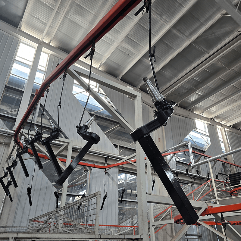
Defining the exact parameters that dictate a successful coating operation is essential. Preserving bath purity relies entirely on maintaining strict thermal boundaries. Paint chemistry is highly reactive, and temperature is the primary catalyst. If you lose control of the temperature, you lose control of the film build, the visual appearance, and the corrosion performance of the final product.
Water-based epoxy paint baths typically require a strict temperature range of 15°C to 30°C (60°F to 85°F). Absolute extreme failure limits span 0°C to 50°C, but operating anywhere outside the standard window severely degrades quality. The chemical formulation relies on this specific thermal band to keep the paint micelles suspended evenly in the deionized water. The emulsion remains stable only when thermal energy is kept low enough to prevent the resins from reacting with each other.
It is vital to differentiate between the low-temperature requirements of the wet bath and the high-temperature requirements of the curing oven. While the bath must remain cool to prevent the paint from reacting prematurely, the final curing stage typically demands 180°C to 190°C (355°F to 375°F) for 20 to 30 minutes. The paint is designed to cross-link and harden at high temperatures. This is exactly why the liquid bath must be kept cool; any excess heat in the tank initiates the curing process while the paint is still in liquid form.
When the bath gets too hot, chemical breakdown begins immediately. Elevated temperatures accelerate solvent evaporation and trigger premature cross-linking within the tank. This leads directly to paint coagulation, commonly referred to as kick-out. The paint solids clump together, separate from the water, and fall out of suspension. This creates a thick, unusable sludge at the bottom of the tank and clogs the ultrafiltration membranes.
Thermal degradation disrupts the standard 1:4 solid-to-liquid ratio, compromising overall bath purity. High temperatures also increase the coating deposition rate unpredictably. The electrical resistance of the bath drops as it heats up, causing the paint to plate much faster than intended at a given voltage. This leads to excessive film thickness. Parts emerge with "orange peel" textures, heavy runs, drips along the lower edges, and massive amounts of wasted coating material. You end up paying for paint that provides no additional structural benefit.
A cold bath introduces entirely different, yet equally severe, defects. Low temperatures increase bath viscosity and raise the electrical resistance of the fluid. The paint becomes thick and sluggish. The rectifiers must work significantly harder to push the same amount of current through the cold liquid. If the rectifiers hit their maximum voltage output, the deposition process stalls.
This increased resistance results in insufficient film build and poor edge coverage. The paint struggles to penetrate Faraday cages or coat complex internal geometries evenly. The "throw power" of the bath diminishes drastically. Parts emerge with inadequate protection, ultimately reducing the salt-spray corrosion resistance of the finished product. Maintaining the lower end of the 15°C threshold is just as critical as preventing overheating. In colder climates, facilities often need to install inline heaters to warm the bath after a long winter weekend shutdown before production can begin.
Troubleshooting Temperature-Induced Coating Defects
Defect Type | Visual Indicator | Thermal Root Cause | Corrective Action |
|---|---|---|---|
Orange Peel | Textured, wavy surface finish resembling fruit skin. | Bath temperature too high, causing rapid, uncontrolled deposition. | Verify chiller output and lower bath setpoint by 2°F increments. |
Thin Film Build | Coating thickness below minimum mil spec, bare edges. | Bath temperature too low, increasing electrical resistance. | Check for overcooling; engage inline heaters if below 60°F. |
Paint Kick-Out | Sludge accumulation in tank, clogged ultrafiltration filters. | Severe overheating causing premature resin cross-linking. | Immediate shutdown; audit heat exchanger for localized hot spots. |
Rupture / Pinholing | Tiny craters or blown-out spots on the cured surface. | High bath temperature causing excessive solvent evaporation. | Stabilize temperature and adjust solvent-to-water ratio. |
Specific hardware extracts heat from the system to maintain equilibrium. Selecting the right components ensures long-term reliability and prevents chemical degradation. You cannot use standard commercial HVAC equipment for this application; the chemical nature of the paint requires specialized industrial cooling infrastructure.
The primary cooling source must match the facility's demands. Air-cooled and water-cooled chillers serve different operational scales. Air-cooled units work well for smaller setups or areas with limited water access. They reject heat directly into the ambient air using large fans and condenser coils. They are easier to install but consume more electricity and struggle in extremely hot ambient environments.
Water-cooled chillers offer higher efficiency for massive, high-BTU/hr requirements. They utilize a secondary cooling tower loop to reject heat. Facility size, ambient climate, and total thermal load dictate the best choice. In high-volume operations, water-cooled systems generally provide more stable leaving water temperatures, which translates to tighter bath control. The compressors in these units—typically rotary screw or centrifugal designs—are built for continuous 24/7 duty cycles.
Plate-and-frame heat exchangers remain the industry standard for electrocoating applications. They offer high thermal efficiency, easy modularity, and straightforward cleaning procedures. The turbulent flow created by the corrugated plates maximizes heat transfer while keeping paint solids suspended. Shell-and-tube designs are rarely used because they are prone to clogging, create low-velocity dead zones, and are exceptionally difficult to clean mechanically.
A strict design constraint exists for any heat exchanger used in this application. Surfaces in direct contact with the bath must never exceed 180°F (82°C). Exceeding this limit causes localized baking. The paint will cure and plate directly onto the 316L stainless steel exchanger plates. This fouling destroys thermal transfer efficiency and requires the unit to be completely dismantled for chemical stripping. Engineers must size the heat exchanger with enough surface area so that the required cooling can be achieved using chilled water temperatures well within safe margins.
The plumbing architecture must route the bath fluid through the heat exchanger carefully. The design must prevent dead zones where paint can settle and coagulate. Piping runs should be as short and straight as possible to minimize pressure drops. Long, convoluted piping networks force the pumps to work harder, generating more mechanical heat.
The system must also avoid excessive shear forces. High shear can mechanically damage the delicate paint emulsion, causing the solids to separate from the water. Smooth, continuous flow dynamics ensure even cooling without compromising the chemical structure of the paint. Engineers typically specify low-shear centrifugal pumps equipped with variable frequency drives to maintain exact flow rates. The velocity through the heat exchanger must remain high enough to prevent settling (typically above 3 feet per second) but low enough to avoid shearing the micelles.
Modern control systems translate raw cooling capacity into precise bath stability. Hardware alone cannot maintain the strict 15°C to 30°C window without intelligent oversight. The thermal loads fluctuate constantly as racks enter and exit the tank, requiring a dynamic, automated response.
Strategic placement of Resistance Temperature Detectors (RTDs) or high-grade thermocouples is critical. Relying on a single sensor creates blind spots. Sensors must monitor the heat exchanger inlet and outlet to calculate real-time thermal transfer efficiency. If the delta between the inlet and outlet drops, the system immediately knows the heat exchanger is fouling.
Additional sensors must track various zones within the main dip tank. Large tanks can develop thermal stratification, where the top layer is significantly warmer than the bottom. A distributed sensing network prevents these localized hot spots from going unnoticed, ensuring the entire bath volume remains uniform. Sensors placed near the overflow weir provide the most accurate reading of the bulk fluid temperature after it has absorbed the heat from the parts.
Programmable Logic Controllers (PLCs) manage the entire cooling infrastructure. They use Proportional-Integral-Derivative (PID) loops to modulate chilled water flow valves in real-time. As the bath temperature rises, the PLC sends a 4-20mA signal to a modulating globe valve, slowly opening it to increase chilled water flow to the heat exchanger.
Proper PID tuning prevents temperature oscillation, known as hunting. Hunting occurs when the system overcorrects, causing the bath temperature to swing wildly up and down. These thermal swings result in inconsistent coating thicknesses across a single production shift. A well-tuned PID loop anticipates the thermal load based on the rate of temperature change and makes micro-adjustments to hold the temperature flat. The proportional band and integral time must be calibrated specifically for the massive thermal inertia of a 10,000-gallon liquid tank.
Automated interlocks protect the system from catastrophic failure. If the bath temperature exceeds critical safety thresholds, the system must react instantly without human intervention. Alarms trigger on the HMI screen, alerting operators to the anomaly, while flashing beacons on the plant floor signal a thermal fault.
More importantly, the PLC must automatically shut down the rectifier. Stopping the DC current immediately halts the largest source of heat generation in the tank. This automated fail-safe prevents total bath loss. Replacing thousands of gallons of ruined e-coat paint is an astronomical expense that redundant controls easily prevent. The circulation pumps remain running during a rectifier fault to continue pushing the fluid through the heat exchanger until safe temperatures are restored.
Procurement and engineering teams must compare vendor proposals using strict frameworks. Evaluating the thermal management system requires looking past the initial purchase price and analyzing long-term operational stability. A cheap chiller will cost a fortune in ruined paint and lost production time.
Calculating the total thermal load requires combining several distinct factors. Engineers must sum the electrical kilowatts from the rectifiers, the pump horsepower, the full-immersion substrate mass, and ambient facility factors. This combined metric sizes the chiller and heat exchanger accurately.
Calculate the maximum electrical heat load by converting the peak rectifier kW output into BTUs per hour.
Calculate the mechanical heat load by converting the total circulation pump horsepower into BTUs per hour.
Determine the substrate thermal load by calculating the mass of metal entering the tank per hour and its temperature differential.
Factor in ambient heat gain through the tank walls during peak summer conditions.
Add a 15% to 20% safety margin to the total sum to account for future production increases or system degradation over time.
Under-sizing leads to severe production bottlenecks. If the chiller cannot keep up, the line must stop while the bath cools down naturally, killing throughput. Over-sizing is equally problematic. An oversized chiller will short-cycle, turning on and off rapidly. This degrades compressor life prematurely and causes poor humidity control around the tank area.
Evaluate the trade-offs between standard cooling systems and high-efficiency variable frequency drive (VFD) chillers. VFD chillers require a higher initial capital expenditure. However, the return on investment for energy-efficient thermal management is rapid in high-volume continuous operations.
VFDs match the cooling output exactly to the real-time load. When the line is running light, or during a shift change, the compressor slows down, drastically reducing electricity consumption. Standard chillers run at full speed constantly, dumping excess capacity and wasting massive amounts of power. Over a ten-year lifecycle, the energy savings from a VFD chiller heavily outweigh the upfront premium.
Retrofitting cooling systems into existing plant layouts presents unique challenges. Space constraints often dictate equipment choices, forcing facilities to place chillers on roofs or far away from the main tank. Long piping runs increase thermal loss, require larger circulation pumps, and complicate maintenance access.
Greenfield installations offer the freedom to optimize the plumbing runs. Engineers can place the chiller and heat exchanger in close proximity to the dip tank. This maximizes efficiency, reduces pressure drops, and ensures maintenance teams have easy access to the equipment for routine servicing. Proper layout planning prevents the cooling infrastructure from becoming an afterthought shoved into a dark corner of the plant.
Operating a temperature control system involves hidden maintenance realities. Ignoring these realities leads to equipment failure and compromised paint quality. The system requires active management to maintain peak thermal transfer efficiency.
Paint solids naturally accumulate on heat exchanger plates over time, regardless of flow dynamics. This fouling degrades thermal transfer efficiency rapidly. As the plates coat with paint, the chiller must work harder to achieve the same cooling effect, and the chilled water valve will remain at 100% open while the bath temperature continues to climb.
Preventative maintenance schedules are mandatory. Facilities must implement regular back-flushing procedures to clear loose debris. Integrating a Clean-In-Place (CIP) system allows operators to flush the heat exchanger with specialized solvents without dismantling the unit.
Isolate the heat exchanger from the main bath using heavy-duty butterfly valves.
Drain the residual paint back into the main tank or a holding tote.
Circulate the manufacturer-approved CIP solvent through the plates to dissolve accumulated resins.
Flush the unit thoroughly with deionized water to remove all solvent traces.
Reintroduce the bath fluid and verify the pressure drop across the plates has returned to baseline.
Chilled water or glycol leaking into the e-coat bath is a catastrophic event. It destroys bath purity and ruins the chemical balance instantly. Introducing foreign water alters the conductivity, while glycol acts as a severe contaminant that causes massive coating defects like cratering and pinholing.
Mitigating this risk requires specific hardware. Double-wall heat exchangers provide a physical barrier against cross-contamination. If an internal plate cracks, the fluid leaks to the atmosphere rather than mixing with the opposing loop. Alternatively, pressure differential monitoring can detect micro-leaks. By keeping the paint side at a higher pressure than the coolant side, any internal rupture pushes paint into the coolant loop, rather than allowing coolant to poison the paint bath. It is much cheaper to flush a chilled water loop than to replace 10,000 gallons of e-coat.
Chilled pipes naturally sweat in high-humidity environments. Condensation forming on overhead chilled water lines can drip directly into the bath or onto unpainted substrates waiting on the conveyor. This introduces untreated water and potential airborne contaminants into the pristine paint emulsion, causing localized defects on the parts.
Proper industrial insulation on all chilled water lines is an absolute necessity. Closed-cell foam insulation with a durable vapor barrier prevents condensation from forming. It also maintains the thermal efficiency of the chilled water loop, ensuring the chiller's energy is spent cooling the bath, not the ambient air. Maintenance teams must inspect this insulation regularly, as forklift damage or maintenance wear can expose bare pipes and create drip hazards.
Precise temperature control is not an auxiliary feature. It is the foundational mechanism that guarantees the chemical stability, purity, and viability of the entire operation. Decision-makers must prioritize vendors who offer integrated PLC controls and easily accessible plate-and-frame heat exchangers. Ensure these exchangers are strictly rated for under 180°F surface temperatures to prevent localized baking. Always demand transparent thermal load calculations before finalizing equipment sizing to ensure the system can handle peak production demands without faltering.
To ensure long-term success and preserve bath purity, follow these actionable steps:
Conduct a comprehensive thermal audit of your proposed throughput to capture all electrical and mechanical heat sources accurately.
Request detailed Piping and Instrumentation Diagrams (P&ID) from equipment suppliers to verify flow dynamics and prevent dead zones.
Verify the physical accessibility and ease of maintenance for all heat exchange surfaces to streamline future Clean-In-Place (CIP) protocols.
Implement redundant temperature sensors across multiple tank zones to eliminate thermal blind spots and prevent localized overheating.
Install pressure differential monitoring on the heat exchanger to detect micro-leaks before coolant can contaminate the paint bath.
A: The standard operating window is 15°C to 30°C (60°F to 85°F). While extreme limits exist (0°C to 50°C), maintaining the strict 15-30°C range is required to preserve the stability of the water-based epoxy or acrylic paint chemistry.
A: Higher bath temperatures decrease electrical resistance and increase the deposition rate, leading to excessive film build, runs, and orange peel textures. Conversely, lower temperatures increase viscosity, resulting in thin, inadequate coatings and poor edge coverage.
A: If the heat exchange surfaces in direct contact with the bath exceed 180°F (82°C), the paint will prematurely cure and plate directly onto the metal plates. This localized baking destroys thermal transfer efficiency and requires extensive downtime to clean.
A: Circulation pumps must turn the entire bath volume over four to six times per hour to keep solids suspended. The mechanical friction and kinetic energy generated by these high-capacity centrifugal pumps transfer directly into the liquid as heat.
A: A coolant leak introduces foreign water, glycol, or anti-corrosion chemicals into the bath. This instantly destroys bath purity, disrupts the delicate chemical balance, and often requires a complete, highly expensive dump and recharge of the entire tank.
A: A PID controller continuously calculates the difference between the actual bath temperature and the target setpoint. It then modulates the chilled water valves in real-time, preventing drastic temperature swings and ensuring consistent coating conditions throughout a production shift.


