

close
Choose Your Site
Global
Social Media
Views: 0 Author: Site Editor Publish Time: 2026-08-28 Origin: Site


Industrial finishing operations face compounding costs from material waste, wastewater treatment, and environmental compliance penalties. Transfer efficiency is a primary metric for profitability on the shop floor. Traditional liquid and powder application methods suffer from unavoidable overspray and significant drag-out. Drag-out is the excess paint carried out of the bath on the surface and inside the cavities of the part. This physical carryover leads to heavy material losses during the subsequent rinse stages if left unmanaged. Transitioning to a modern electrophoretic coating line addresses this inefficiency directly through closed-loop recovery systems and precise electrochemical controls. By integrating ultrafiltration technology and counter-flowing rinse cascades, manufacturers capture un-deposited paint solids before they reach the drain. This closed-loop architecture enables facilities to achieve near 100% material utilization while minimizing effluent discharge.
Closed-Loop Recovery: Ultrafiltration (UF) technology captures up to 98% of un-deposited paint solids from the rinse zones and returns them to the active electrocoating bath.
Parameter Dependency: Paint loss during rinsing is heavily dictated by bath chemistry; improper pH, temperature, or voltage can cause newly deposited films to re-dissolve or wash away.
Quality Retention: Preventing rinse-stage paint loss is essential not only for cost savings but for preserving the high-gloss finish and strong anti-corrosive properties expected from e-coated parts.
Cost vs. Compliance: Investing in advanced rinse-recovery systems within a coating line reduces raw material expenditure while simultaneously simplifying wastewater compliance.
Maintenance Realities: Sustaining high recovery rates requires rigorous monitoring of UF membrane health and rinse water conductivity to prevent fouling and cross-contamination.
Ultrafiltration serves as the primary engine for material recovery in an electrocoating system. The UF unit continuously draws fluid from the main dip tank and forces it under pressure through semi-permeable membranes. This mechanical process separates the complex paint bath into two distinct streams. The first stream contains the concentrated paint solids, resins, and pigments. The second stream, known as permeate, consists entirely of water and low-molecular-weight solvents. By extracting water directly from the paint mix to generate this rinse permeate, facilities drastically minimize their intake of fresh municipal water.
The closed-loop cycle relies on routing this permeate directly to the post-coat rinse zones. As coated parts exit the main bath, the permeate sprays over them to wash away un-deposited paint. The system collects this fluid mixture in the rinse tanks below. Because the permeate shares the exact chemical makeup of the bath's liquid phase, it seamlessly cascades back into the primary electrophoretic tank. This continuous loop ensures near-zero material loss and maintains the volumetric balance of the entire system.
Membrane selection dictates recovery efficiency on the production floor. Spiral wound membranes offer high surface area and excellent permeate flux rates, making them standard in high-production environments. Tubular membranes provide better resistance to plugging from large particulates but require a larger physical footprint. Plant engineers must match the membrane type to the specific paint chemistry and anticipated production volumes to ensure a steady supply of wash water. Operating these membranes requires strict attention to trans-membrane pressure. If the feed pumps push the fluid too hard, the paint solids will compact against the membrane surface, blinding the pores and halting permeate production.
Drag-out is the physical carryover of bath liquid on complex part geometries as they emerge from the dip tank. Parts with deep recesses, internal channels, or folded seams trap significant volumes of un-deposited paint. Automotive subframes, agricultural equipment chassis, and stamped brackets with hem flanges are notorious for carrying excess fluid. Without a dedicated recovery mechanism, this excess material washes straight down the drain. A modern Coating Line employs a multi-stage counter-flowing rinse architecture to capture this fluid efficiently.
The physical architecture of a counter-flowing rinse system relies on gravity and strategic pump placement to move fluid against the direction of part travel. Here is the standard sequence of operations for capturing drag-out:
The coated part exits the primary dip tank and enters the first ultrafiltration rinse zone (UF1), where high-volume headers spray the part to knock off the heaviest layer of un-deposited paint.
The fluid collected in the UF1 tank, now heavily laden with recovered paint solids, overflows directly back into the primary dip tank to replenish the bath.
The part advances to the UF2 and UF3 zones, where progressively cleaner permeate washes the remaining solids from the surface and internal cavities.
Clean permeate from the ultrafiltration unit feeds directly into the UF3 tank. As UF3 fills, it overflows backward into UF2, which subsequently overflows into UF1.
The part receives a final wash in a virgin Deionized (DI) water halo to remove any trace solvents or conductive ions before entering the curing oven.
This cascading method concentrates the recovered solids step-by-step. It pushes the paint back toward the primary tank without diluting the active bath chemistry. By the time the part reaches the final DI water halo, the surface is virtually free of un-deposited solids. This architecture creates a highly efficient recovery loop that captures drag-out before it ever leaves the system envelope.
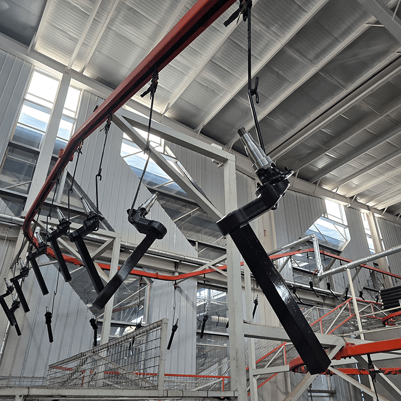
Bath chemistry dictates the physical stability of the applied film. Operators must maintain the pH of the electrophoretic tank within a strict operational window. During the cathodic electrodeposition process, the chemical reaction deposits positively charged paint particles onto the grounded part. This reaction leaves behind excess neutralizing agents, typically organic acids like acetic or lactic acid. If the pH drops too low and the bath becomes overly acidic, a severe chemical risk emerges during the wash stage.
When the pH falls out of specification, the newly deposited coating will re-dissolve into the rinse water. This reverse reaction results in thin films, exposed edges, and excessive material loss during the washing phase. The paint simply washes off the part and overloads the ultrafiltration recovery loop, eventually causing the solids to drop out of suspension entirely. Operators will notice the rinse tanks turning milky or opaque, a clear indicator that the film is stripping off the substrate.
Facilities utilize anolyte systems, also known as dialysis cells, to prevent this chemical degradation. These cells sit inside the main dip tank along the side walls. They consist of a semi-permeable membrane surrounding a bare anode. As the electrical current drives the paint to the part, the excess acid migrates through the membrane into the anolyte fluid. A dedicated pump circulates this fluid, flushing the neutralizing agents out to a drain or collection tote. By stabilizing the pH levels automatically, anolyte systems ensure the wet paint film remains intact and durable as it passes through the high-pressure rinse zones.
Bath temperature directly influences coating deposition efficiency, fluid viscosity, and ultimate film density. Operating outside the specified temperature window compromises the coating effect and weakens the internal structure of the film. A bath that is too cold results in a highly viscous paint that deposits unevenly, creating a thick, unstable layer that easily washes away. A bath that is too hot accelerates the reaction too quickly, creating a porous, rough surface known as solvent popping. A weak film cannot withstand the mechanical force of the rinse sprays, leading to immediate paint loss.
Applied voltage plays an equally critical role in film integrity. For example, in red copper electrophoretic coating, insufficient voltage yields a fragile film with poor adhesion to the substrate. The rinse stage easily strips away this weak layer, exposing bare metal. Conversely, excessive voltage causes film rupture and pinholing. High voltage forces the coating to build too fast, trapping gases underneath the film. When these gas bubbles burst, they leave microscopic craters that trap rinse water and cause severe cosmetic defects during the curing process.
To maintain strict parameter tolerances, operators rely on automated rectifiers and thermal management systems. Rectifiers utilize step-voltage programming to apply power gradually as the part enters the bath. This soft-start prevents electrical surging and ensures a dense, uniform deposition. Simultaneously, chilling and heating exchangers regulate bath temperature to within a single degree of the target setpoint. Consistent parameters guarantee a durable film build that survives the aggressive washing process without shedding material.
Process Parameter Troubleshooting Guide
Parameter | Optimal Condition | Risk if Out of Specification | Corrective Action |
|---|---|---|---|
Bath pH Level | Strictly within vendor spec (e.g., 5.5 - 6.0) | Film re-dissolves in rinse; thin edges; poor corrosion resistance. | Flush anolyte cells; check dialysis membrane integrity; adjust acid/base feed. |
Bath Temperature | Typically 27°C - 32°C (80°F - 90°F) | Porous film structure; low deposition efficiency; rough surface finish. | Inspect chiller/heater loop; clean heat exchanger plates; verify flow rates. |
Applied Voltage | Dependent on part geometry and line speed | Weak film stripped by rinse sprays (low voltage); film rupture (high voltage). | Calibrate rectifier; implement step-voltage programming; check anode positioning. |
Permeate Flow Rate | Sufficient to maintain clean final rinse | Inadequate washing; drag-out bakes onto part; cosmetic defects. | Perform chemical CIP on UF membranes; replace pre-filters; check pump pressure. |
Integrating high-capacity UF modules requires a significant upfront capital expenditure. Facilities must purchase the membrane housings, high-pressure circulation pumps, and complex piping manifolds. However, the financial evaluation must weigh this initial cost against the long-term reduction in paint consumption. Traditional air-atomized spray processes suffer from overspray, which remains an unavoidable and unrecoverable loss. Even with electrostatic bells, spray transfer efficiency rarely exceeds 70%. A dip-based system inherently eliminates overspray entirely.
This operational shift makes drag-out recovery the sole focus for achieving material yields exceeding 95%. When the recovery system functions correctly, facilities only pay for the paint that actually cures on the part. The return on investment for a robust ultrafiltration system is often realized within the first few years of operation simply through the drastic reduction in raw material purchases. Plant managers can track this efficiency by monitoring the ratio of dry film weight on the finished parts versus the volume of liquid paint added to the replenishment tanks.
Part geometry and line speed dictate the volume of drag-out and directly influence the required capital expenditure. Complex parts with deep recesses carry more fluid out of the bath. Engineers must size the recovery system based on these specific variables. Proper sizing ensures the UF modules can process the required volume of permeate to wash the parts effectively. Undersized systems bottleneck production and force operators to use fresh water for rinsing, which destroys the closed-loop efficiency and generates massive volumes of wastewater.
Rinse-stage efficiency directly impacts final product quality and field performance. Excessive paint loss during the wash stage reduces the final film build below the manufacturer's specification. A thin film severely compromises the part's strong anti-corrosive properties. Parts subjected to standard salt spray testing will fail prematurely if the edges and internal cavities lose their protective coating during the rinse cascade. The mechanical force of the spray headers will easily strip a poorly deposited film from sharp laser-cut edges, leading to early rust formation in the field.
Strict parameter control prevents re-dissolution in the rinse zones. When the film remains stable during washing, the curing oven bakes it into a uniform, highly durable barrier. This is particularly critical for demanding aesthetic standards, such as achieving a flawless high-gloss black finish. Proper rinsing removes un-deposited solids that would otherwise bake into the surface as dirt seeds, drips, or sags. If the UF system fails to provide enough clean permeate, the drag-out will dry on the part before it reaches the oven, creating a rough, sandpaper-like texture.
The final DI water rinse plays a major role in aesthetic preservation. Any dissolved solids left on the part will create water spots or wash-marks during the curing phase. By ensuring the recovery loop functions perfectly, operators keep the final rinse stages pristine. This guarantees a smooth finish free from thin spots, craters, or chemical staining. Maintaining the DI halo under 10 micro-siemens of conductivity is a standard operational requirement for Class A finishes.
Capturing paint solids before they enter the waste stream drastically lowers biological and chemical oxygen demand (BOD/COD) in facility effluent. Uncured paint resins and organic solvents place a massive load on wastewater treatment systems. Environmental compliance becomes much easier to manage when the primary source of chemical contamination is recycled directly back into the production tank. Instead of treating thousands of gallons of paint-laden water daily, the facility only treats the small volume of overflow from the pretreatment stages.
Closed-loop rinsing architectures actively support Zero Liquid Discharge (ZLD) initiatives. By continuously recycling permeate and minimizing fresh water intake, facilities reduce the volumetric burden on downstream wastewater treatment plants. The system only discharges a small amount of ultrafiltration permeate during routine maintenance, membrane cleaning, or complete color changes. This drastically shrinks the footprint of the on-site wastewater treatment plant.
This sustainable approach cuts sludge disposal costs and mitigates the risk of environmental compliance penalties. Facilities avoid the heavy surcharges associated with discharging high concentrations of heavy metals or volatile organic compounds (VOCs) into municipal sewers. The recovery system transforms a major environmental liability into a reusable production asset, keeping the plant compliant with local discharge permits.
The primary operational risk in any closed-loop recovery system is membrane fouling. UF membranes operate under high pressure to force water through microscopic pores. Over time, these pores become clogged by biological growth, resin agglomeration, or particulate contamination. Once fouled, permeate production drops significantly. This starves the rinse zones of clean wash water and causes paint solids to build up on the parts, leading to immediate quality rejections.
Operators mitigate this risk by implementing routine chemical cleaning-in-place (CIP) protocols. CIP cycles utilize specialized acid or alkaline cleaners to strip away resin buildup and restore membrane permeability. An alkaline wash typically removes organic resin fouling, while an acid wash targets inorganic scale and metal hydroxides. The frequency of CIP depends on production volume and bath stability, but regular maintenance is non-negotiable for system longevity.
Monitoring permeate flux rates provides early warning signs of fouling. A sudden drop in flow indicates an immediate need for cleaning or filter replacement. Maintaining proper pre-filtration before the UF unit is equally critical. Bag filters capture large particulates, weld slag, and metal shavings before they reach the expensive membrane elements. Upgrading to multi-stage bag filtration extends the operational lifespan of the membranes and prevents catastrophic physical damage to the spiral wound layers.
Contamination entering the dip tank from upstream processes poses a severe threat to the recovery loop. Drag-in contamination, such as carryover from pretreatment chemicals, alkaline cleaners, or zinc phosphates, alters the chemical balance of the entire system. This drag-in directly affects the conductivity of the rinse water. High conductivity destabilizes the recovered paint, causing the resins to coagulate or drop out of suspension inside the rinse tanks. Once the paint coagulates, it cannot be pumped back into the main bath and must be shoveled out as hazardous waste.
Preventing this failure requires strict conductivity monitoring throughout the pretreatment and rinse cascades. Operators must ensure parts are thoroughly rinsed before entering the electrocoating bath. Automated sensors track the micro-siemens levels in each tank and trigger alarms if contamination spikes. If the DI water rinse before the e-coat tank exceeds 30 micro-siemens, the line should automatically halt to prevent bath poisoning.
Facilities strategically use Reverse Osmosis (RO) or Deionized (DI) water in the final rinse stages prior to the dip tank and in the final post-coat rinse. This ensures the fluid touching the part is completely free of dissolved solids. Maintaining low conductivity guarantees a pristine finish and protects the main bath from chemical imbalance, ensuring the recovered paint remains viable for re-application.
Conduct a facility audit to quantify current drag-out losses and identify parts with high fluid retention geometries.
Evaluate existing wastewater treatment costs to determine the exact return on investment for installing a closed-loop ultrafiltration recovery system.
Consult with an integration engineer to specify the appropriate ultrafiltration membrane sizing based on your line speed and required permeate flow rates.
Implement automated conductivity and pH monitoring sensors across all active rinse stages to prevent chemical destabilization and film re-dissolution.
Establish a strict chemical cleaning-in-place (CIP) schedule for all filtration membranes to prevent fouling and maintain consistent wash water production.
A: With proper ultrafiltration and closed-loop rinsing, transfer efficiency typically exceeds 95%. This is a massive improvement compared to the 50-70% efficiency seen in traditional liquid or powder spray methods. The high efficiency results directly from the complete elimination of overspray and the continuous recycling of un-deposited paint solids back into the main tank.
A: Ultrafiltration separates the paint bath into reusable solids and clear permeate. The system forces the bath fluid through semi-permeable membranes under high pressure, extracting water and solvents directly from the mix. This generated permeate is then routed to the post-coat rinse zones to wash parts and recover drag-out.
A: E-coat washes off primarily due to poor bath chemistry or incorrect application parameters. An improperly high pH causes the newly deposited film to re-dissolve. Additionally, low applied voltage results in weak deposition, while incorrect bath temperatures compromise overall film density, making the coating susceptible to high-pressure rinse sprays.
A: Drag-out is the excess, un-deposited paint solution that physically clings to a part as it exits the dip tank. Complex part geometries trap more fluid in cavities and recesses. This excess material must be rinsed off and recovered through counter-flowing cascades to maintain high material efficiency and prevent defects.
A: Operators maintain pH using anolyte or catholyte systems, also known as dialysis cells. These systems utilize continuous chemical monitoring to actively remove the excess neutralizing agents generated during the electrodeposition process. This continuous flushing keeps the bath chemistry stable and prevents film re-dissolution.
A: Yes, through the use of counter-flowing rinses and ultrafiltration, the vast majority of water and paint solids are captured and recycled back into the main process tank. This closed-loop approach minimizes wastewater generation, reduces chemical oxygen demand, and strongly supports facility environmental compliance initiatives.


