

close
Choose Your Site
Global
Social Media
Views: 0 Author: Site Editor Publish Time: 2026-08-25 Origin: Site


The highest failure point in electrodeposition is rarely the electrical current. It is the physical instability of the paint bath itself. Static or poorly circulated paint baths inevitably lead to pigment settling, severe thermal gradients, and localized pH imbalances. These conditions directly result in costly coating defects. You will see pinholes, uneven film build, and cratering on the final substrate. This drives up reject rates and compromises anti-corrosive properties.
Continuous, engineered paint bath circulation acts as the primary control mechanism. It maintains suspension homogeneity across the entire tank, manages heat loads effectively, recovers excess paint, and ensures consistent yield in your industrial setup. A robust circulation system keeps the chemistry stable. It guarantees that every part receives a uniform, high-quality finish regardless of production volume. Without aggressive fluid dynamics, the physics of the bath will actively work against your coating quality.
Suspension Stability: Continuous circulation prevents the agglomeration and settling of heavy pigment and resin particles in the water-based bath.
Thermal Control: Circulation dissipates the heat generated by the electrical resistance (Joule heating) during the coating process, preventing premature paint curing in the tank.
Contamination Mitigation: Integrated filtration within the circulation loop removes particulates and chemical drag-in originating from the Pretreatment System.
Paint Recovery & Waste Reduction: Circulation drives the ultrafiltration (UF) process, allowing for the recycling of non-deposited paint and drastically reducing waste liquid discharge.
System Sizing is Critical: Improperly sized pumps or poorly mapped eductor nozzles create dead zones or induce paint shear, degrading the coating material over time.
To understand bath circulation, you must first understand the fundamental nature of e-coat materials. The paint used in an electrophoretic coating line consists of positively or negatively charged resin and pigment particles. These particles are suspended in a water-based medium. They are not dissolved. This distinction dictates the entire engineering approach to the system. The fluid is a delicate emulsion relying on electrostatic repulsion and mechanical agitation to keep particles apart.
The primary threat to this emulsion is gravity. There are significant specific gravity differences between the heavy paint solids and the lighter carrier liquid. Gravity causes rapid settling without continuous mechanical intervention. Pigments like titanium dioxide or carbon black will drop to the tank floor. Resins will separate and float or coagulate. Once this settling occurs, it is often irreversible. The paint loses its structural integrity and becomes useless sludge that must be physically shoveled out of the tank.
Specific Gravity Comparison in Standard E-Coat Baths
Component | Approximate Specific Gravity | Behavior in Stagnant Bath |
|---|---|---|
Deionized Water (Carrier) | 1.00 | Remains neutral; forms the continuous phase. |
Epoxy or Acrylic Resins | 1.10 - 1.20 | Slow settling; prone to coagulation if shear is applied. |
Carbon Black Pigment | 1.80 - 2.10 | Moderate settling; accumulates in low-flow corners. |
Titanium Dioxide Pigment | 3.90 - 4.20 | Rapid settling; drops immediately without high-velocity agitation. |
The baseline requirement for a successful bath is absolute uniformity. You must maintain a uniform solid content percentage across every cubic inch of the tank. You must also maintain a uniform temperature profile. Meeting these success criteria guarantees high-gloss finishes. It ensures strong anti-corrosive properties on the final substrate. Plant engineers design circulation systems specifically to fight the specific gravity differentials shown above.
Continuous tank turnover is an absolute necessity. Most systems require the entire volume of the tank to turn over 4 to 6 times per hour. For a 10,000-gallon tank, the pumps must move 40,000 to 60,000 gallons per hour. This rapid movement keeps solids in a state of uniform suspension. It prevents the heavier pigments from separating from the lighter resins.
Homogeneous solid distribution ensures consistent film thickness. When a workpiece enters the bath, the electrical field draws the suspended particles to the metal. If the bath is well-mixed, complex geometries receive an even coating. Recessed areas, internal cavities, and sharp edges build the correct film thickness. A stagnant bath leads to thin spots on upper surfaces and thick, sagging paint on lower surfaces where pigments have pooled.
The thermodynamics of electrocoating require strict attention. The electrical current passing through the bath generates significant heat. This is known as Joule heating. The bath acts as a massive resistor in the electrical circuit. As rectifiers push hundreds of amps through the fluid, temperatures rise rapidly. Every watt of electrical power consumed translates directly into heat energy within the liquid.
The circulation system routes the heated paint through external heat exchangers. These chillers maintain a strict temperature window. The standard operating range is usually 80°F to 90°F (26°C to 32°C). If the bath gets too hot, solvents flash off prematurely. The resin begins to degrade or cure inside the tank, ruining the entire batch. If it gets too cold, the coating efficiency drops, resulting in thin film builds and poor adhesion.
Filtration housings are integrated directly within the main circulation loop. As the pumps move the paint, a portion of the flow passes through these filter arrays. This is the primary defense against physical contamination. Standard setups utilize heavy-duty stainless steel housings equipped with synthetic filter bags.
The filters capture physical debris, metal fines, and coagulated paint particles. Weld slag, grinding dust, or dirt from the factory floor inevitably finds its way into the tank. If these particles are not removed, they will adhere to the workpiece. They become permanently baked into the finish inside the curing oven, causing visible surface defects, seediness, and potential rust points.
Electrocoating is a dynamic chemical process. As paint deposits onto the part, counter-ions are left behind in the bath. In a cathodic epoxy system, this usually means an accumulation of acetic or lactic acid. This alters the pH and conductivity. Circulation prevents the localized pooling of these acids near the electrodes. It ensures that the chemical composition remains uniform throughout the tank.
Circulation also plays a role in feeding the anolyte or catholyte systems. These systems maintain the delicate chemical balance by flushing the anolyte cells. They ensure the counter-electrodes remain clean. Clean electrodes allow the electrical circuit to complete efficiently. This prevents localized resistance buildup, which would otherwise require higher voltages to achieve the same coating thickness, wasting energy and generating excess heat.
The main circulation pumps feed the ultrafiltration system. This system separates the carrier liquid from the paint solids. The resulting clear liquid is called permeate. UF membranes allow water and solvents to pass through while retaining the larger pigment and resin molecules. The concentrated paint returns directly to the main tank.
This continuous loop creates a closed-loop recovery system. The permeate is routed to the post-rinse stages. It washes excess, non-deposited paint (cream coat) off the exiting parts. This rinsed paint is then recycled back into the active bath. This process significantly reduces the production and discharge of waste liquid. It drastically lowers material costs and environmental compliance burdens, capturing up to 98% of the paint solids.
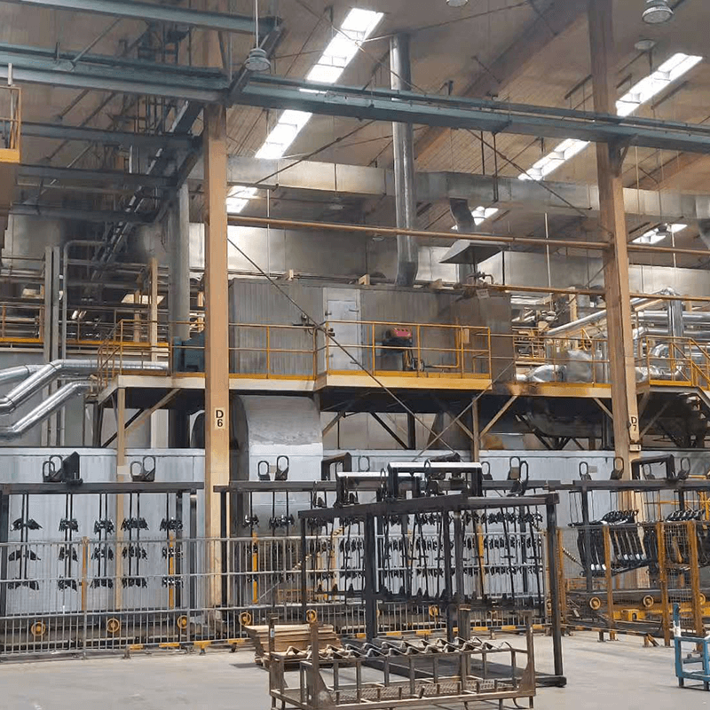
Workpieces do not enter the e-coat tank in a pristine state. They carry residual chemicals and water from the Pretreatment System. This phenomenon is known as drag-in. Even with excellent drainage angles and air blow-offs, complex parts trap liquids in seams, hem flanges, and blind holes. These liquids mix directly into the paint bath as the part submerges.
Aggressive circulation and filtration dilute and isolate these contaminants. The rapid turnover ensures that drag-in does not create concentrated pockets of pretreatment chemicals. Unreacted zinc phosphate or alkaline cleaners can alter the bath conductivity. They can destabilize the emulsion and cause the paint to kick out of suspension. Proper circulation maintains overall coating purity despite continuous drag-in from the upstream stages.
A failure upstream creates a cascading failure downstream. Inadequate cleaning or poor phosphating in the pretreatment stages leads to higher particulate loads in the e-coat tank. Oils, drawing compounds, soils, and unreacted phosphate crystals wash off into the paint. Oil is particularly damaging, as it causes cratering and fish-eyes in the cured film.
This overloads the bath filtration system. You will face frequent filter bag replacements, sometimes daily instead of weekly. Beyond consumable costs, severe contamination causes premature paint degradation. The entire bath may require chemical additions, solvent bumps, or, in worst-case scenarios, a complete dump and recharge. The circulation system can only handle a finite amount of upstream negligence before the paint chemistry collapses.
Circulation Component Specifications
Component Category | Standard Technology | Primary Function | Key Evaluation Metric |
|---|---|---|---|
Main Circulation Pumps | Low-Shear Centrifugal | Drive tank turnover and feed UF/Chillers | Shear sensitivity and flow rate (GPM) |
Tank Agitation | Venturi Eductor Nozzles | Multiply fluid flow within the tank | Flow multiplication ratio (typically 5:1) |
Filtration Housings | Dual-Bag Stainless Steel | Remove particulates and debris | Micron rating (25 to 50 microns) |
Heat Exchangers | Plate and Frame Chillers | Remove Joule heating from the bath | BTU removal capacity per hour |
Pump selection requires evaluating shear sensitivity. Paint emulsions are fragile. High mechanical shear will physically destroy the paint emulsion. It tears the resin micelles apart, causing the paint to coagulate in the piping. Once sheared, the paint cannot be repaired and will clog the ultrafiltration membranes.
Low-shear centrifugal pumps are the industry standard. They move large volumes of fluid without imparting excessive mechanical force. Engineers specify pumps operating at lower speeds (e.g., 1150 RPM or 1750 RPM) rather than high-speed 3600 RPM models. Positive displacement pumps are generally avoided for main circulation. Their tight tolerances and aggressive pumping action create too much shear. Always specify pumps with open impellers and double mechanical seals equipped with a deionized water flush to prevent paint from curing on the seal faces.
Moving fluid through pipes is not enough. You must agitate the fluid inside the tank. The solution approach involves eductor nozzles mounted on submerged manifolds. These mixing nozzles use the Venturi effect. They draw in surrounding fluid, multiplying the pump flow by up to five times. If you pump 100 GPM through the nozzle, it moves 500 GPM of fluid within the tank.
You must evaluate the engineering required to map nozzle placement. Poor placement creates dead zones. These are areas of low flow, particularly in tank corners or bottoms. Sludge will accumulate in these zones. Proper mapping ensures sweeping flow across the entire tank floor, directing settled solids back up into the main fluid body. Nozzles are typically angled at 45 degrees downward to sweep the floor and create a rolling action in the bath.
Filter specifications must map directly to your finish quality requirements. Standard industrial applications use 25 to 50-micron filter bags. High-gloss automotive finishes may require tighter filtration, down to 10 microns. Tighter filters capture smaller particles but require more frequent changes and higher pumping pressures.
Scalability is a major factor. You should utilize dual-housing (duplex) filtration setups. This allows operators to isolate one housing using butterfly valves and change the filter bag while the other housing remains active. You can perform maintenance without halting the circulation line. Stopping circulation, even for a few minutes, risks paint settling. Operators monitor differential pressure gauges across the filter housings to determine exactly when a bag is blinded and requires replacement.
Undersized piping or improperly specified pumps cause cavitation. Cavitation occurs when the fluid pressure drops below its vapor pressure at the pump inlet. This introduces micro-bubbles into the bath. These bubbles travel through the system and attach to the workpiece. They manifest as pinholes on the cured part, exposing bare metal to corrosion.
Mitigation requires strict adherence to fluid velocity guidelines. Header pipes should maintain velocities of 10 to 12 feet per second. You must also perform proper Net Positive Suction Head (NPSH) calculations. Ensure the pump inlet receives adequate fluid pressure to prevent vapor formation. Avoid sharp 90-degree elbows and restrictive valves in the suction line. Use long-radius sweeps and properly sized suction headers to feed the pumps smoothly.
Poor manifold design leads to localized settling. When parts pass through a dead zone, they encounter fluid with a lower solid content and poor temperature control. This causes those parts to receive inadequate film build. It severely compromises their corrosion resistance and field performance, leading to premature warranty claims.
Mitigate this risk by utilizing computational fluid dynamics (CFD) modeling during the tank design phase. CFD verifies flow patterns before steel is welded. It allows engineers to adjust eductor angles and manifold spacing. This ensures uniform velocity gradients across the entire working envelope of the tank. During annual shutdowns, physically inspect the empty tank for sludge patterns to verify the CFD model matches reality.
Running high-horsepower pumps 24/7/365 presents a high energy cost. Circulation cannot stop, even during non-production hours, holidays, or weekend shutdowns. Stopping the pumps guarantees catastrophic paint settling, which can cost tens of thousands of dollars in lost paint and downtime.
Implement Variable Frequency Drives (VFDs) to manage this cost. VFDs allow you to lower pump speeds during off-shift hours. You can dial back the flow to maintain minimum suspension velocities (usually dropping from 6 turnovers per hour down to 2 or 3). This keeps the paint stable while drastically reducing energy consumption. When production resumes, the VFDs ramp the pumps back up to full operational flow rates to handle the heat load and drag-in.
Conduct a baseline audit of your current tank turnover rates to ensure they meet the 4-6 times per hour standard required for stable suspension.
Install differential pressure gauges on all filtration housings and establish a strict replacement schedule based on pressure drops rather than arbitrary timeframes.
Review your pretreatment carryover by measuring the conductivity spikes in the e-coat bath, adjusting upstream drainage angles to minimize chemical drag-in.
Inspect the tank floor during the next scheduled drain cycle to locate sludge buildup, using this data to adjust eductor nozzle angles and eliminate dead zones.
Implement Variable Frequency Drives on main circulation pumps to establish a low-energy weekend mode that maintains minimum flow without wasting electricity.
A: The standard turnover rate is 4 to 6 times per hour. This rapid circulation ensures homogeneous particle suspension and consistent temperature control. The exact rate depends on the specific paint chemistry, pigment density, and tank geometry. High-density pigments require turnover rates closer to the higher end of this spectrum to prevent settling.
A: No. Circulation must run 24/7 to prevent irreversible settling of the paint solids. If the pumps stop, the emulsion breaks down and heavy pigments drop to the tank floor. However, pump speeds can be safely reduced during off-shifts using Variable Frequency Drives (VFDs) to save energy while maintaining minimum suspension velocities.
A: Poor pretreatment introduces particulates, oils, and chemical drag-in into the e-coat bath. This overloads the circulation filtration system, requiring frequent filter changes. Chemical drag-in can also alter the bath conductivity and pH, forcing the circulation system to work harder to dilute and isolate these contaminants to prevent paint destabilization.
A: Circulation pumps feed the ultrafiltration (UF) system. The UF system separates the carrier liquid (permeate) from the paint solids. This permeate is used to rinse non-deposited paint off the parts as they exit the bath. The rinsed paint is then recycled back into the active tank, minimizing waste liquid discharge and lowering material costs.
A: Paint shear is caused by excessive mechanical force acting on the fragile paint emulsion. High-rpm positive displacement pumps, sharp pipe elbows, undersized piping, and excessive fluid velocities can tear the resin micelles apart. This degrades the paint, causing it to coagulate in the pipes and create surface defects on the parts.
A: Eductor nozzles use the Venturi effect to multiply fluid flow by up to five times without introducing moving parts into the bath. Mechanical agitators create excessive shear, which damages the paint emulsion. Eductors provide sweeping, low-shear agitation that effectively eliminates dead zones and keeps solids suspended across the entire tank.
A: Dead zones are detected through physical inspections and part monitoring. During annual tank drains, inspect the tank floor and corners for hardened sludge buildup. During production, monitor parts for localized coating thickness variations. Consistently thin film builds on specific areas of the parts often indicate they are passing through a low-flow dead zone.


